Description
Table of Contents
- 1. Introduction of Pneumatic Rotary Valve Actuator
- 2. Double Acting Actuator Working Principle
- 3. Pneumatic Actuator Specification & Torque
- 4. Double Acting Actuator Selection
Introduction of Pneumatic Rotary Valve Actuator
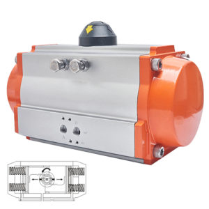
What is a pneumatic rotary actuator? Firstly, AT series pneumatic piston actuator has two types: direct acting and reverse acting air torque actuator. The positive actuator means: while the signal pressure increases, then push rod goes downward. On the contrary, the meaning of reverse acting pneumatic actuator is below. When signal pressure increases, the push rod goes upward. In short, the output displacement of this pneumatic valve actuator is directly proportional to the input air pressure signal. That is to say, the greater the signal pressure, the greater the displacement of the push rod.
The pneumatic actuator is piston type. The pneumatic piston actuator has a long stroke. And it is suitable for occasions requiring greater thrust. We can apply the pneumatic rotary actuator together with valve accessories: valve positioners, solenoid valves, limit switches, handwheel mechanisms, air filter pressure reducing valves, etc. Due to many advantages, pneumatic valve actuator has wide application in many industries, such as chemical, oil refining, pharmaceutical, etc.
In conclusion, air torque actuator is an actuator powered by compressed air. Pneumatic acting actuator applications are as follows,such as ball valves, butterfly valves, plug valves, etc. It has the these characteristics, such as simple structure, convenient operation and stable work. Therefore, pneumatic rotating actuator has been wide application in the automatic adjustment and remote control of the production process. For example, automatic temperature control of superheated steam in power plants. If together with the positioner, it can continuously receive control commands and output linear displacement. At this time, the positioner and the actuator form a closed loop. So it can regulate the flow characteristics and action form of control valves.
Double Acting Actuator Working Principle

Pneumatic Actuator Specification & Torque
Actuator rotation angle: 90°±5°
Applicable air source: 0.25~0.8MPa;
Air source interface: accord with NRMAR standard;
Action form: double acting actuator;
Ambient temperature: standard type -20℃~+80℃;
Outer casing material: muti-layer aluminum alloy.
The Output Torque of Double Acting Actuator:
| Model | Air Source Pressure (Mpa) | |||||
| 0.3 | 0.4 | 0.5 | 0.6 | 0.7 | 0.8 | |
| Output Torque (MM) | ||||||
| AT52 | 12 | 16 | 20 | 24 | 28 | 32 |
| AT63 | 21.7 | 28.9 | 36.1 | 43.4 | 50.6 | 57.8 |
| AT75 | 35 | 46.6 | 58.3 | 69.9 | 81.6 | 93.2 |
| AT83 | 42.8 | 57 | 71.3 | 85.5 | 99.8 | 114 |
| AT92 | 67.6 | 90.1 | 112.6 | 135.2 | 157.7 | 180.2 |
| AT105 | 97.7 | 130.3 | 162.9 | 195.5 | 228 | 260.6 |
| AT125 | 173.3 | 231 | 288.8 | 346.5 | 404.3 | 462 |
| AT140 | 260.7 | 347.6 | 434.5 | 521.4 | 608.3 | 695.2 |
| AT160 | 397.2 | 529.6 | 662 | 794.4 | 926.8 | 1059.2 |
| AT190 | 640.2 | 853.6 | 1067 | 1280.4 | 1493.8 | 1707.2 |
| AT210 | 798 | 1064 | 1330 | 1596 | 1862 | 2128 |
| AT240 | 1154 | 1539 | 1924 | 2308 | 2693 | 3078 |
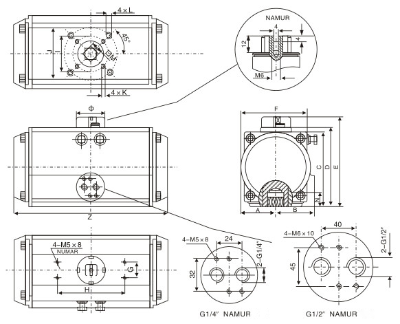
Dimensions of Pneumatic Rotary Actuator:
| Model | A | B | C | D | E | F | G | H | I | J | K | L | M | N | Z | Φ | Air Source Port |
| AT52 | 30 | 41.5 | 65.5 | 72 | 92 | 65 | 30 | 80 | Φ36 | Φ50 | M5*8 | M6*10 | 11 | 14 | 147 | Φ40 | NAMUR G1/4″ |
| AT63 | 36 | 47 | 81 | 87.5 | 107.5 | 72 | 30 | 80 | Φ50 | Φ70 | M6*10 | M8*13 | 14 | 18 | 168 | Φ40 | NAMUR G1/4″ |
| AT75 | 42 | 53 | 94 | 99.5 | 119.5 | 81 | 30 | 80 | Φ50 | Φ70 | M6*10 | M8*13 | 14 | 18 | 184 | Φ40 | NAMUR G1/4″ |
| AT83 | 46 | 57 | 98.5 | 108.7 | 128.7 | 92 | 30 | 80 | Φ50 | Φ70 | M6*10 | M8*13 | 17 | 21 | 204 | Φ40 | NAMUR G1/4″ |
| AT92 | 50 | 58.5 | 111 | 116.5 | 136.5 | 98 | 30 | 80 | Φ50 | Φ70 | M6*10 | M8*13 | 17 | 21 | 262 | Φ46 | NAMUR G1/4″ |
| AT105 | 57.5 | 64 | 122.5 | 133 | 153 | 109.5 | 30 | 80 | Φ70 | Φ102 | M8*13 | M10*16 | 22 | 26 | 268 | Φ46 | NAMUR G1/4″ |
| AT125 | 67.5 | 74.5 | 145.5 | 155 | 185 | 127.5 | 30 | 130 | Φ70 | Φ102 | M8*13 | M10*16 | 22 | 26 | 301 | Φ46 | NAMUR G1/4″ |
| AT140 | 75 | 77 | 161 | 172 | 202 | 137.5 | 30 | 130 | Φ102 | Φ125 | M10*16 | M12*20 | 27 | 31 | 390 | Φ60 | NAMUR G1/4″ |
| AT160 | 87 | 87 | 184 | 197 | 227 | 158 | 30 | 130 | Φ102 | Φ125 | M10*16 | M12*20 | 27 | 31 | 458 | Φ60 | NAMUR G1/4″ |
| AT190 | 103 | 103 | 216 | 230 | 260 | 189 | 30 | 130 | Φ140 | M16*25 | 36 | 40 | 525 | Φ60 | NAMUR G1/4″ | ||
| AT210 | 113 | 113 | 235.5 | 255 | 285 | 210 | 30 | 130 | Φ140 | M16*25 | 36 | 40 | 532 | Φ60 | NAMUR G1/4″ | ||
| AT240 | 130 | 130 | 264.5 | 289 | 319 | 245 | 30 | 130 | Φ165 | M20*25 | 46 | 50 | 602 | Φ60 | NAMUR G1/4″ |
Double Acting Actuator Selection
Firstly, determine the torque required to open and close the valve. When selecting a pneumatic rotary actuator, add a safety value to the torque of the determined valve. Under normal use conditions, the recommended safety factor is 15-20%. If it’s water vapor or non-lubricating liquid medium, increase the safety value by 25%. If non-lubricating slurry liquid medium, increase the safety value by 40%. For non-lubricating granular powder medium, it needs increase the safety value by 60%.
For example, Controlling a ball valve requires a torque of 200Nm. At the same time, the air source pressure is 0.5MPa. And the medium is steam. Considering safety factors, thus it increases the safety value by 25%. Then the torque is equal to 250Nm. Firstly, find the air source pressure of 0.5MPa according to the double-acting actuator output torque table. Then find the torque data that is equal to or similar along the column vertically. So choose 288.8Nm. Finally, look for its number to the left along the line and select AT125 actuator.
Pneumatic Actuator Structure
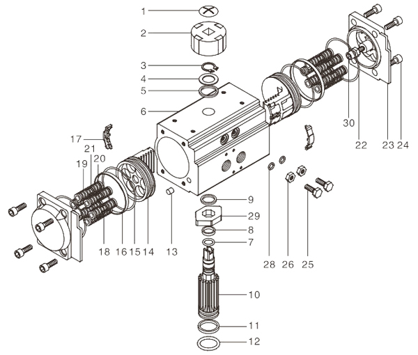
| No. | Parts Name | Q’ty | Material |
| 1 | Indicator Screw | 1 | Stainless Steel |
| 2 | Indicator | 1 | Plastic |
| 3 | Circlip | 1 | Stainless Steel |
| 4 | Gasket | 1 | Stainless Steel |
| 5 | Outer Gasket | 1 | Engineering Plastics |
| 6 | Cylinder Block | 1 | Cast Aluminum |
| 7 | Upper Shaft O Ring | 1 | Fluorine rubber, nitrile rubber |
| 8 | Upper Shaft Bearing | 1 | Engineering Plastics |
| 9 | Inner Gasket | 1 | Engineering Plastics |
| 10 | Shaft | 1 | Alloy Steel |
| 11 | Lower Shaft Bearing | 1 | Engineering Plastics |
| 12 | Lower Shaft O Ring | 1 | Fluorine rubber, nitrile rubber |
| 13 | Plug | 2 | Rubber |
| 14 | Piston | 2 | Cast Aluminum / Steel |
| 15 | Piston O Ring | 2 | Fluorine rubber, nitrile rubber |
| 16 | Poston Bearing | 2 | Engineering Plastics |
| 17 | Piston Baffle | 2 | Nylon |
| 18 | Spring | * | Spring Steel |
| 19 | Spring left sleeve | * | Nylon |
| 20 | Spring right sleeve | * | Nylon |
| 21 | Spring sleeve connecting rod | * | Copper |
| 22 | End Cap O Ring | 2 | Fluorine rubber, nitrile rubber |
| 23 | End Cover | 2 | Cast Aluminum |
| 24 | End Cover Bolt | 8 | Stainless Steel |
| 25 | Adjusting Bolt | 2 | Stainless Steel |
| 26 | Adjusting Screw Nut | 2 | Stainless Steel |
| 27 | Adjusting Screw Gasket | 2 | Stainless Steel |
| 28 | Adjusting Screw O Ring | 2 | Fluorine rubber, nitrile rubber |
| 29 | Cam | 1 | Alloy Steel |
| 30 | Limiting Nut | 2 | Stainless Steel |
Advantages & Features of Double Acting Air Actuator
1) Firstly the warranty period of our pneumatic rotary actuator is 18 months. In addition, the service life of the double acting actuator reaches 1 million times.
2) Secondly, the extruded aluminum alloy cylinder body is hard-oxidized. Moreover, the pneumatic piston actuator has a hard surface texture. So it’s waterproof, anti-sliding, anti-corrosion. Further, we take strict quality inspection before leaving the factory.
3) Dual-piston gear and rack-and-pinion structure. Accurate meshing and smooth transmission. Moreover, the installation position is symmetrical and the output torque is constant.
4) Compact structure and beautiful appearance. it is not only lightweight, but also easy to install. So it can disassemble and assemble the double acting pneumatic actuator conveniently .
5) It can adjust double acting actuator in both directions of plus or minus 5 degrees at 0° and 90°. Thus it ensure that the valve opens and closes exactly.
6) In addition, the actuator indicator complies with the VID/VIE3845 NAM UR standard. So it’s easy to install limit switches, positioners and other accessories.
7) There are a variety of shapes for the installation and connection holes of the output shaft.
8) The piston ring of air cylinder actuator is made of low-friction, long-life composite material. So it is convenient for maintenance and replacement.
9) Air source interface: in line with NAM UR standard, NAM UR standard. So the solenoid valve can be directly installed.
10) Finally, all fasteners of air torque actuator are made of stainless steel.
Installation & Usage of Double Pneumatic Actuator
Firstly, pneumatic rotary actuator is a device for remote operation of process valve. Then depending on the option, it can use the double acting actuator to permit the opening or closing of the valve rotation. When installing double acting pneumatic actuators and valves, there must be correct technical data. Such as model specifications, output torque, air capacity, stroke adjustment, action time and operating temperature.
Important Safety Notice
1. When assembling pneumatic rotary actuator, it cannot supply air and pressurize at any time. Otherwise, loss of parts may occur.
2. The connecting pipes & fittings associated with the actuator must be clean. Further, it’s free of waste.
3. When installing accessories on the double acting actuator, there must be proper space, in order to undetake rother operations.
4. Before installing the valve, firstly determine the position of the air torque actuator and valve. Secondly consider which direction you need to rotate in. In addition, the two must be consistent.
5. It should use pneumatic rotary actuators within the specified air source pressure range. Otherwise, the operation and use exceeding the air supply pressure will damage the actuator.
6. In addition, operation beyond the temperature limit will damage the internal parts and the spring return will fail.
7. Incorrect anti-corrosion operating environment not only may damage the internal parts, but also external parts of the double acting pneumatic actuator.
Other Safety Notices:
8. Firstly do not disassemble the spring assembly at will. Otherwise, it will lead to spring ejection and injury to the operator.
9. During maintenance, the air source must be cut off. Most importantly, it can only repair actuator after the pressure is drained.
10. When there is pressure, do not disassemble the end cap and disassemble the double acting valve actuator.
11. Before assembling the actuator and the valve, make sure that the valve opening and closing position and the indicated position are the same.
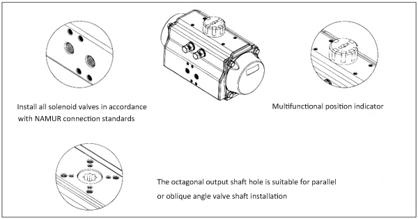
Installation of pneumatic rotary actuators and valves, solenoid valves and limit switches
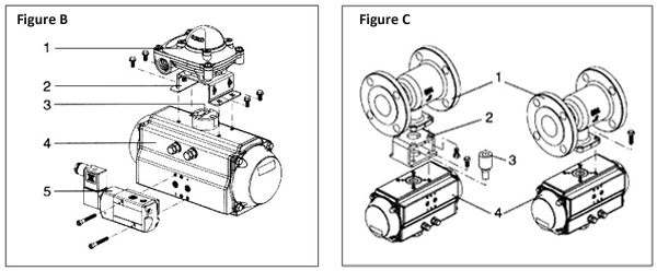
Install the solenoid valves and limit switches
Firstly before installing the solenoid valve (5), make sure that it is in the normal position (closed position) together with the double acting actuator (4). Secondly in the standard assembly combination, the direction of rotation is clockwise as OFF. Thirdly at the same time, the groove on the indicator 3 must be aligned with the closed position of the actuator 4. Finally the mark of the solenoid valve 5 and the mark of the actuator 4 are aligned and installed.
Immediately afterwards, install the limit switch. Firstly, when installing the limit switch 1, make sure that the display is closed. Secondly, align the groove on the indicator 3 through the bracket 2. Finally, install it with four bolts.
Install the double acting actuator on the valve
Before installing the pneumatic rotary actuator on the valve, firstly determine the correct selection direction of the actuator and the valve. Or consider which direction to choose when supplying air. When use a single acting actuator, the direction of rotation of its reset should match the direction of rotation of the valve (that is to say, to reach the open or closed position). There are two ways to install the double acting actuator on the valve:
(1) The first type is to install directly. Firstly, the valve 1 with the installation platform and the valve stem must meet the connection dimensions of the ISO5122 standard. Immediately afterwards, insert it directly into the output mounting hole of the actuator 4 for installation.
(2) The second type is to install through the bracket. That is to say, install the valve on the pneumatic rotary actuator through a bracket 2 and a connecting sleeve 3. In addition, use the connecting sleeve the output torque of the actuator to the valve stem.
Maintenance & Troubleshooting of Double Acting Pneumatic Actuator
Pneumatic valve can’t move
1. Firstly, check whether the solenoid valve is normal. Secondly check whether the coil is burned out. Finally check whether the solenoid valve core is stuck by stolen goods——Solutions are as follows: replace the solenoid valve, replace the coil, and clear the dirty stuff.
2. Immediately afterwards, check whether the single gas supply of the pneumatic rotary actuator is working normally. For example, check whether there is the blow-by of the cylinder piston. Meanwhile, check if there is air leakage at the cylinder block and end cover, etc. In addition, disassemble the pneumatic rotary actuator to check if the seal is damaged. Meanwhile, check if the surface of the cylinder bore is damaged——The solutions are below: replace the damaged seal ring, replace the cylinder or piston.
3. Meanwhile, check if the impurity in the valve jams the ball core——clear the impurity, and replace the damaged valve.
4. Subsequently, check if the handle of handwheel is in the manual position——pull the handle to the pneumatic automatic position.
5. In addition, check if the pipeline is twisted——correct or replace the pipeline.
6. Finally, check if the medium or ambient temperature is too low, thus causing the pipeline to freeze——clear the condensate in time and add water removal equipment.
Pneumatic valve action is slow and crawling
1. Firstly, perhaps insufficient air source pressure——increase air source pressure. Or install an air tank, in order to reduce pressure fluctuations.
2. Secondly, the flow is perhaps not enough——add air storage tank and add air compressor to reduce pressure fluctuation.
3. Thirdly, the torque of the pneumatic rotary actuator is perhaps too small——increase the actuator specification.
4. In addition, the valve load is perhaps too heavy. Or the valve core or other valve parts are assembled too tightly. Thus it needs assemble valve again, in order to adjust the valve torque.
5. Because of large changes in the friction of the cylinder, take proper lubrication.
The limit switch has no signal
1. Firstly, the signal power line is perhaps short-circuited. So it needs repair the power line.
2. Because of inaccurate cam position, it needs re-adjust the cam to the correct position.
3. Finally, the micro switch is perhaps damaged. Thus replace the micro switch.
Disassembly & Assembly of Pneumatic Piston Actuator
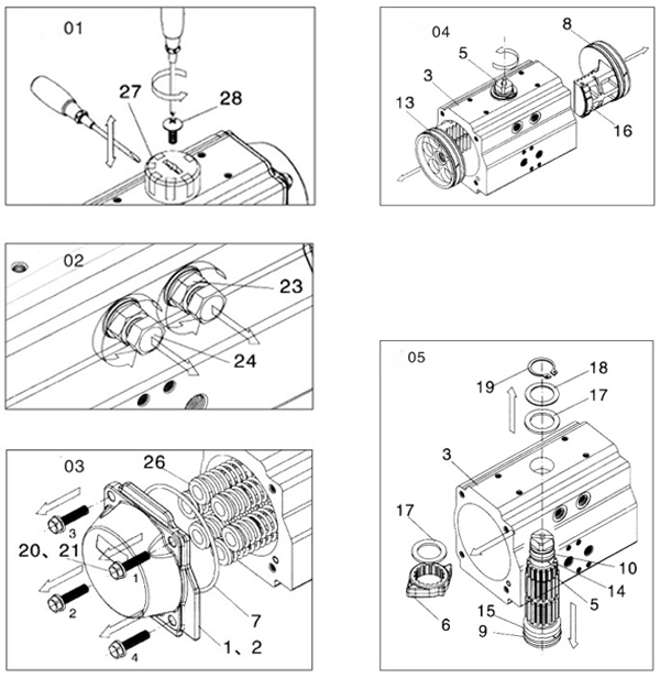
How to disassemble single & double acting actuator?
In order to maintain the actuator, sometimes we need to disassemble it. Firstly, separate the pneumatic rotary actuator from the valve. Before disassembling, make sure that the actuator is not supplied with air pressure. Meanwhile, remove all accessories. Finally if it is a single acting actuator, make sure that the spring of the actuator must be reset.
(1) Disassembly of indicator of pneumatic rotary actuator (part 27) (Figure 01)
Firstly, use a cross screwdriver to disassemble the large flat head screws (28);
In addition, it may need a straight screwdriver to gently pry the position indicator (27).
(2) Disassemble adjusting bolt of single & double acting pneumatic actuator (part 24) (Picture 02)
First of all, use a wrench to loosen and remove the hexagon head bolt (24) together with the nut (23) and gasket (22);
Then, remove the obsolete O-rings on the screws that need to be replaced.
(3) Disassembly of end caps of pneumatic rotary actuator (parts 1 and 2) (Figure 03)
Firstly, remove the end cap hexagon head bolts (20 and 21) in order. When removing a single acting actuator, turn and loosen the end cap hexagon head bolts (20 and 21). Immediately afterwards, the end cap will loosen naturally. If it can’t loosen the end cap, the sleeve of the spring assembly (26) may be damaged. At this time, it needs to disassemble it carefully. Moreover, take safety measures to avoid injury.
Because the single acting pneumatic actuator must remove the spring assembly (26).
Finally, remove the end cap O-ring (7). If damaged, it can be replaced.
(4) Disassemble the piston (part 4) (Figure 04)
Firstly, use a tool such as a vise to fix the cylinder body of pneumatic rotary actuator. Then rotate the output shaft (5) until the two pistons (4) are released. It is forbidden to use air pressure to eject the piston from the cylinder with pressure.
Secondly, use a straight screwdriver to remove the piston O-ring (8). Immediately afterwards, remove the piston bearing (13) and guide bearing (16). Finally replace the obsolete O-rings and bearings.
(5) Disassemble the output shaft of of single & double acting actuator (part 5) (Figure 06)
Firstly, use a pliers tool to remove the retaining ring (19). Then remove the upper gasket (18) and thrust bearing (17).
Immediately afterwards, push the output shaft (5) down firmly to a suitable height. Then take out the adjusting cam (6) and thrust bearing (17) from the actuator cylinder (3). Finally safely remove the output shaft (5) from the bottom of the pneumatic rotary actuator. If it is difficult to remove the output shaft, you can use a mallet or plastic hammer to gently tap the top of the shaft.
Finally, remove the bearings (14) and (15) on the top and bottom of the output shaft, and the O-rings (9) and (10). Then replace the discarded bearings (14) and (15), thrust washer (17) and O-rings (9) and (10).
How to assemble pneumatic rotary actuator?
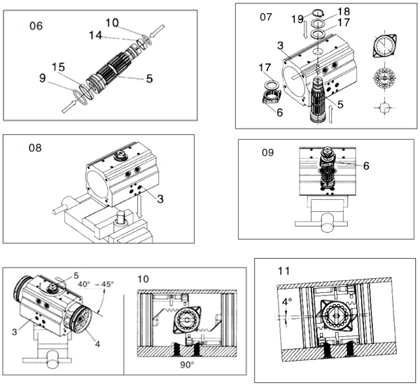
(1) The assembly of the output shaft (5) (Figure 06 and 07)
Firstly, assemble the bearings (14), (15) and O-rings (9) and (10) on the top and bottom of the output shaft;
Secondly, apply grease to the surface of the output shaft. Then insert the output shaft (5) into the bottom hole of the pneumatic rotary actuator(3) to a suitable height. At this time, insert the adjusting cam (6) into the correct position on the top of the output shaft through the hole in the cylinder body (Figure 7). And then install the thrust bearing (17). Finally, insert the output shaft completely into the single & double acting actuator.
Finally, install the outer thrust bearing (17) and gasket (18). Then use a pliers tool to install the circlip (19).
(2) Assemble the piston of pneumatic rotary actuator (part 4) (Figures 08, 09, 10 and 11)
Firstly, install the piston O-ring (8), guide bearing (16) and bearing (13).
Then apply grease to the inner hole of the actuator (3) and the surface of the piston (4) and the rack.
Immediately afterwards, use a vise tool to clamp the corrected square-headed shaft. And then Insert it into the output shaft hole. Finally connect the output shaft and the cylinder block. And then it will support the pneumatic rotary actuator (3) to form a horizontal position (see Figure 08).
Thirdly, make sure that the adjusting cam (6) is in the center position as shown in Figure 09.
And then for the standard actuator assembly (clockwise to close), rotate the cylinder (3) about 40°~45°. As shown in Figure 10.
The two pistons (4) in the cylinder (3) simultaneously squeeze toward the middle. Until the piston rack and gear bite to complete the cylinder rotation and stroke.
Finally, when the piston is inserted into the double acting actuator, check the fully closed and open positions. As shown in Figure 11.
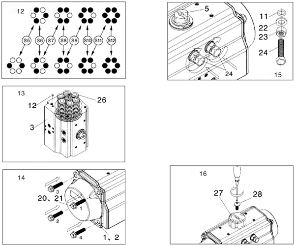
(3) Assembly of end cap (left end of part 1 and right end of part 2) and spring assembly (26) (Figure 12, 13 and 14)
Firstly, apply grease to the bore of the pneumatic rotary actuator.
Secondly, insert the assembled spring assembly (26) into the piston tailstock in an appropriate amount according to the model shown in Figure 12. As shown in Figure 13.
Then, insert rubber seal plugs (12) at both ends of the air torque actuator (3) (Figure 13).
Immediately afterwards, install the O-rings (7) into the ring grooves on the end faces of the two end caps.
Finally, install the end cap hexagon head bolts (20 and 21) (Figure 14). When assembling a single acting pneumatic actuator, it must tighten each part must one by one according to the sequence number.
(4) Assembly of adjusting bolt and stroke adjustment (part 24) (Figure 15)
Firstly, install the nut (23), gasket (22) and O-ring (11) on the adjusting bolt (24) in sequence. And then the standard pneumatic rotary actuator refers to the adjustment that closes in a clockwise direction.
Secondly, adjustment of 0° (closed) position. The single & double acting actuator is in the closed position. And then view the straight groove at the top of the reference output shaft (5) from above. Then turn the adjusting bolt (24) to the proper position. Finally tighten the nut (23).
Immediately afterwards, adjustment of 90° (open) position. The single & double acting actuator is in the open position. And then view the straight groove at the top of the reference output shaft (5) from above. Then turn the adjusting bolt (24) to the proper position. Finally tighten the nut (23).
(5) Assembly of position indicator (parts 27 and 28) (Figure 16)
Firstly, after checking the position of the pneumatic rotary actuator, install the position indicator (27).
Then, use the large flat head screws (28) to properly lock the position indicator.
Storage guidance:
If you do not use the pneumatic rotary actuator immediately, you must save it as follows:
1. Firstly, store in a dry environment at room temperature;
2. It is recommended to store the actuator in the original packing box;
3. Finally, do not remove the plastic plug on the air supply port.
FAQ of Double Acting Actuator Pneumatic
Q1: What is the difference between pneumatic rotary actuator and linear actuator?
A1: When rotary actuator working, its torque is arc-shaped. Because this is consistent with the motion path when ball valve and butterfly valve opening and closing, it can work more efficiently in matching. But air linear actuator generally reciprocate in a straight line.
Q2: Double acting actuator vs single acting
A2: Single acting spring return actuator: The opening stroke or closing stroke is provided by compressed air. But the stroke in the other direction is generally provided by the springs.
Double acting pneumatic actuator: Both the opening stroke and the closing stroke of the double-acting actuator are provided by compressed air.
Q3: How about double acting actuator fail position?
A3: In the case of loss of air supply, the double acting valve actuator can only remain in its original position. But single-acting pneumatic piston actuators are generally used in safety situations. In the event of a system failure (loss of air), it can ensure that the valve is in a safe position (open or closed) through a spring.
Q4: How long is the service life of your pneumatic rotary actuator?
A4: After testing, our single acting and double acting non spring return actuator have a lifetime of up to one million times.




Reviews
There are no reviews yet.